|
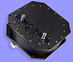
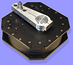
The Jefa RG10-100 reduction gearbox transforms a rotational movement into
a push-pull movement. The reduction gearbox is always positioned close to
the rudder stock. Via a draglink with rose joints, the push-pull movement
is transmitted to the tiller lever and rudder shaft. The RG10 gearbox is
very versatile as it can be equipped with one (standard), or two input
shafts. On top of that one can choose the output shaft at the opposite
side of the input shafts (type 1) or at the same side (type 2). The gear
ratio is 1:10 (3.5 revolutions of the input shaft for a corresponding 72
degrees of rudder travel). This can be increased with steps of 1.2:1 by
using step ratio bevel boxes (4.3 turns with one step ratio and 5.2 turns
with two step ratio bevel boxes). The output lever centres are 165 mm to a
corresponding 250 mm centres of the tiller lever or 200 mm to a
corresponding 307 mm of the tiller lever. This difference in length
results in the so called "wide angle geometry". Please click
here for more in depth explanation. The RG10-100 gearbox has 4 positions
to integrate an optional Jefa transmission autopilot drive unit.
Integrating an autopilot drive in a steering system has never been so
easy. The maximum input torque is 40.5 kgfm resulting in a maximum rudder
torque at full rudder of 1183 kgfm. The maximum rudder torque according to
the CE rating is 410 kgfm midships and 788 kgfm full rudder (the CE
regulations use a safety factor of 150%). This makes the gearbox suitable
for boats from 60' to around 95'. Except for the input shafts and the
gears, the complete gearbox is machined out of solid aluminium 6082 for
maximum strength and minimum weight (26,5 Kgs). Positioning the reduction gearbox
correctly to the rudderstock is very important for the wide angle geometry
to function correctly. Please look at the mounting examples at the bottom
of this page. As the RG10-100 gearbox is a two stage gearbox, the rotation is reversed. Please notice this fact when setting up the rotations. This gearbox uses Ø22 mm pins and the heavy duty version of our draglinks. The pin on the gearbox is included, the pin for the tiller arm has to be ordered separately. Please click on the pictures for a larger view. |
|